In 2026, a coil’s resistance remains a practical clue to its condition, not a complete diagnosis. It influences current and copper losses, while temperature, supply voltage, and operating frequency also shape performance. Why proper coil resistance matters becomes clear when a motor runs hot, a solenoid responds sluggishly, or a transformer winding shows an unexpected reading. Small changes matter.
The U.S. Department of Energy’s Improving Motor and Drive System Performance: A Sourcebook for Industry identifies winding losses as part of motor energy losses. IEEE Std 112 also sets out recognized procedures for testing induction-motor performance. These references support a careful approach: measure consistently, record winding temperature, and compare results with manufacturer specifications or a verified baseline. A resistance value without those details can mislead.
Copper resistance rises as winding temperature increases, so a warm coil may read higher than the same coil when cold. That is measurable. Yet resistance alone cannot reveal every fault; insulation damage, loose connections, and shorted turns may require additional tests. I have seen one overlooked detail undermine an otherwise tidy diagnosis: the meter leads were not accounted for when checking a very low-resistance winding. It is a reminder that good practice is not always elegant. This introduction sets up the key questions: what resistance indicates, how to measure it reliably, and when a reading calls for further investigation.
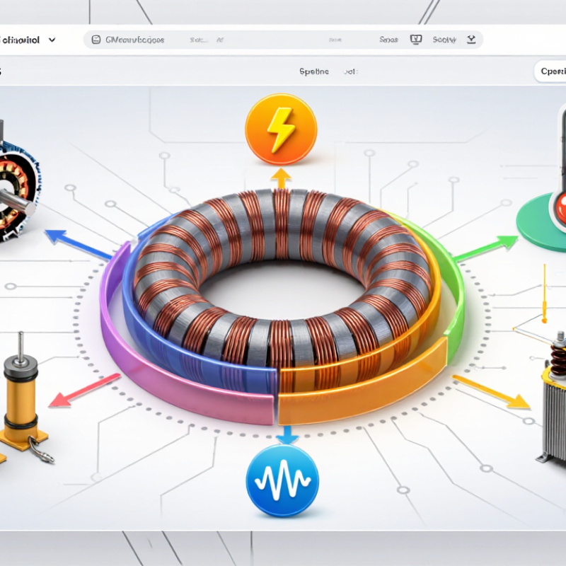
Coil resistance is the opposition a winding offers to electric current, measured in ohms. A meter measures it by applying a small voltage and sensing the resulting current; the relationship is R = V/I. For a uniform wire, resistance can also be estimated with R = ρL/A, where ρ is the material’s resistivity, L is wire length, and A is its cross-sectional area. Simple, but not perfect.
NBS Handbook 100, a U.S. National Bureau of Standards reference, gives copper’s resistivity near 20°C as about 1.724 × 10⁻⁸ ohm-metres. Using that value, two metres of copper wire with a 0.5-millimetre diameter has an estimated resistance of about 0.18 ohms. Real measurements may differ. Lead wires, terminal contact, winding geometry, and temperature all affect the reading. Copper’s resistance rises by roughly 0.393% per °C near room temperature, so a warm coil can read higher than a cool one. For very low resistance, a four-wire measurement helps reduce lead error. The calculation is a useful check, not a substitute for careful measurement.
A coil’s resistance helps determine how much current flows and how much electrical power becomes heat. With a fixed 12-volt supply, a 6-ohm coil draws 2 amps and uses 24 watts. Lower resistance draws more current from that same supply. That can create more heat, but only if the power source can safely provide it. Too much current may overheat the coil, wiring, or nearby components. Too little power may leave the coil cooler than intended. Small differences matter.
Tips: Check the coil’s rated resistance and the power source’s limits before connecting them. Measure resistance with suitable equipment, and inspect connections for looseness or corrosion. Never assume a warm coil means the system is operating correctly.
The relationship changes with the control system. A regulated device may adjust its voltage to maintain a set power, so resistance alone does not predict temperature. Coil material, wire thickness, airflow, and contact quality also affect heating. In practice, I would check both the resistance and the operating current rather than rely on a label. It is easy to overlook a poor connection. A quick measurement can catch that mistake.
Proper coil resistance matters because it affects current, heat, and power. At a fixed voltage, lower resistance draws more current. The relationship is simple: power equals voltage squared divided by resistance. For example, at 4 volts, a 1-ohm coil draws 4 amps and uses 16 watts; a 0.5-ohm coil draws 8 amps and uses 32 watts. These are illustrative calculations, not recommended settings. Small changes matter. Excess heat can damage a coil, degrade its materials, or strain a battery. Match the coil to the device’s specified resistance and power range. Check for loose connections, too; a number alone cannot confirm safe operation.
The US Fire Administration’s report on electronic-cigarette fires and explosions documented 195 incidents from 2009 to 2016, with 133 acute injuries. Those figures do not show that coil resistance caused the incidents. They do show why battery and device safety deserve attention alongside performance. I would not treat a resistance reading as a safety certificate. Measure carefully, follow device instructions, and stop using a setup that heats unusually or behaves inconsistently. In 2026, reliable resistance measurement remains useful, but it is only one part of a safer system.
Choosing and checking coil resistance in 2026 starts with the coil’s specification, not a guess. Resistance affects current draw and heat, so a mismatch can cause poor performance or overheating. Switch off and disconnect the equipment before testing. Let the coil cool, then measure across its terminals with a suitable meter. Small details matter: loose clips and dirty contacts can distort a reading.
Compare your measurement with the specified resistance and the coil’s operating limits. NIST’s Copper Wire Tables, published as NBS Handbook 100, give copper’s temperature coefficient as about 0.00393 per °C near room temperature. Resistance therefore rises as a copper coil warms. A reading taken hot may differ from its stated room-temperature value. For very low resistance, ordinary meter leads can also affect the result. I still double-check the setup; it is easy to blame the coil too soon.
Tips: Test at room temperature, clean the contact points, and record the reading. If it varies sharply or falls outside the specification, stop using the assembly and inspect its connections. Don’t compensate by increasing power. Resistance alone does not confirm that a coil is safe; check the full equipment rating and follow the manufacturer’s instructions.
Why coil resistance matters: At a fixed 3.7 V, lower resistance draws more current. Values shown are theoretical calculations using Ohm’s law (I = V ÷ R); real devices may differ because of voltage sag, regulation, and other electrical limits. Resistance alone does not determine whether a setup is safe—check the device and battery specifications.
Proper coil resistance still matters in 2026, but emerging designs may make the old “lower is better” rule less useful. Newer coil structures can spread heat across wider surfaces, while improved sensors may track temperature and power more closely. That shifts attention toward the whole system: coil material, wire geometry, insulation, airflow, and rated output. Resistance remains a key measurement, not a complete performance score.
Some designs may use thinner conductors, layered meshes, or materials with more stable resistance as they warm. These changes could allow tighter control, but they do not guarantee one ideal resistance target. A controller using temperature feedback may behave differently from a fixed-output circuit. Two coils with the same measured resistance can still heat unevenly or respond at different speeds. Small differences matter. There may not be one shared standard yet, and that uncertainty deserves attention.
Tips: Check the device’s stated resistance range and power limits before use. Measure resistance with a suitable meter, inspect connections for looseness, and stop if readings fluctuate unexpectedly. When comparing coil designs, note warm-up time and heat consistency, not just the ohm value. Keep records; patterns can be more useful than one test.
It measures how strongly a coil opposes electric current. The unit is the ohm.
Use R = V/I, where voltage is divided by current. For uniform wire, estimate resistance with R = ρL/A.
A 0.5-millimetre diameter wire may measure about 0.18 ohms near 20°C. Real readings can differ.
Copper resistance rises by about 0.393% per °C near room temperature. A warm coil may read higher than a cool one.
Switch off and disconnect the equipment. Let the coil cool, then measure across its terminals.
Loose clips, dirty contacts, lead wires, and terminal contact can affect results. Small details matter.
A four-wire measurement helps reduce errors from meter leads. Check the setup carefully; I sometimes recheck the clips.
Stop using the assembly and inspect its connections. Don’t increase power to compensate. Resistance alone does not prove the equipment is safe.
Why proper coil resistance matters is that resistance determines how much current flows through a coil and how electrical energy becomes heat. It is commonly calculated by dividing voltage by current, while power can be estimated from voltage and current or from resistance and current. A resistance that is too low may draw excessive current and create more heat than the system can safely manage; one that is too high may limit current and reduce performance. Choosing a suitable value helps balance efficiency, temperature, reliability, and safe operation.
In 2026, select resistance according to the device’s specifications and intended operating range rather than relying on assumptions. Check the coil with an appropriate meter, inspect connections, and replace damaged or inconsistent components. New materials, finer manufacturing, and improved temperature-control systems may allow coils to perform effectively at different resistance levels. These advances can broaden design options, but they do not remove the need to verify compatibility and monitor heat and electrical limits.

Trivapix Vape